

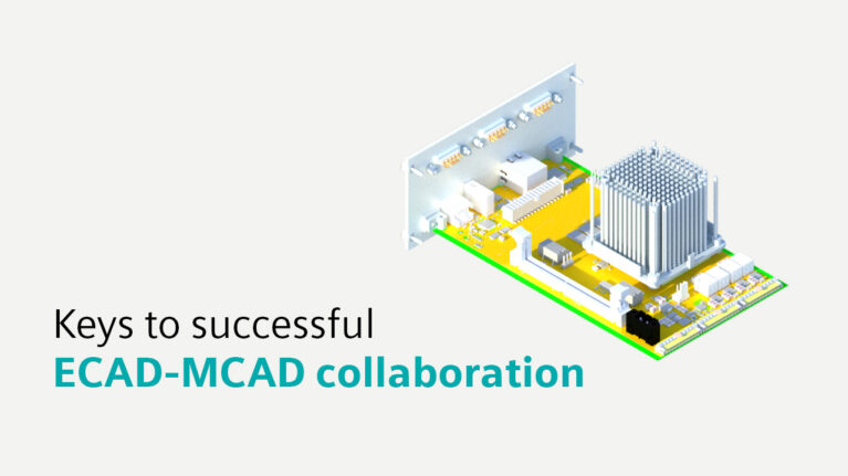
In the highly complex landscape of modern product development, the synchronization between Electronic Computer-Aided Design (ECAD) and Mechanical Computer-Aided Design (MCAD) teams is a strict engineering imperative. As hardware architectures evolve to feature increasingly compact IC packages and high-density printed circuit boards (PCBs), integrated cross-domain collaboration is no longer optional.
The Need for ECAD-MCAD Integration
Combining mechanical structures with electronic components creates specific engineering problems. As products shrink, electrical interference and physical collisions happen more often.
To solve this, mechanical and electrical engineers need software that lets them communicate instantly. When both sides use a shared platform, they can spot conflicts early and fix them before manufacturing begins. An integrated setup lets teams push small updates back and forth without losing data, keeping the entire project aligned and preventing expensive late-stage changes.
Key Advantages of MCAD-ECAD Collaboration Design
- Better Productivity: Working together streamlines the workflow. Engineers can test different layouts inside their own software at the same time. This parallel workflow prevents delays and speeds up output.
- Shift-left design & verification: Good integration tools allow teams to move testing to the start of the project. Instead of building physical models, teams run digital tests to check for errors, which helps launch products faster.
- First-pass success: Checking data constantly during the drafting phase stops big mistakes from reaching the factory floor. Catching clearance or interference issues early means the final product will likely work on the first try.
- Digital thread & Digital twin: Connecting both domains helps companies maintain a reliable digital thread. This builds an accurate virtual copy (digital twin) of the product, ensuring the parts fit perfectly before any real assembly happens.
Solving Data Sharing Problems
The hardest part of joining these two fields is keeping everyone updated on design changes. Data must flow smoothly to avoid mismatched versions.
Software tools should handle this automatically using the IDX file standard. The IDX format tracks and sends only the exact changes made. This means engineers do not have to guess if they are looking at the newest file, allowing them to focus on designing.
A model-based design strategy is also required. Instead of relying on static documents, teams build 3D models and data sets. This creates a solid foundation for the product’s digital twin.
Working Concurrently with Model-Based Systems
When using a model-centric approach, electrical and mechanical tasks happen simultaneously. This setup removes duplicate data entry and relies on virtual testing to catch flaws. Because it limits the need to build physical test units, companies save money and finish projects sooner.
Final Thoughts
Since electronic and mechanical parts are now deeply connected, teamwork between departments is vital. Hardware makers need the right software and a model-based strategy to succeed. By uniting these processes, companies can cut design times, lower costs, and build better products.
(Source: Siemens)
Discover more:
- Webinar: Optimizing Design with Automation and MCAD–ECAD Integration in the Electronics Industry
- Seamless Collaboration with MCAD/ECAD Integration Solution
- Rigid-flex PCB design with Xpedition Standard
Contact VBTECH for personalized advice: